


| PART # | REQUIRED | DESCRIPTION |
| VH-01CC | 4 | Round Head Machine Screw, #10-32 x 3/8” |
| CM-663 | 1 | Breather Cover (41753 thru 41969, C-10001 & Later) |
| CM-664 | 1 | Breather Valve |
| CM-665 | 1 | Gasket (Breather Cover)(41753 thru 41969, C-10001 & Later) |
| CM-701 | 1 | Crankcase with Oil Cup |
| CM-702 | 2 | Low Pressure Cylinder |
| CM-703 | 1 | High Pressure Cylinder |
| CM-711 | 1 | Large End Plate with Cup #r-641 |
| CM-712 | 1 | Side Door w/Breather Port**Furnish(1) CM-785,(2) CM-728, (1) |
| CM-786, (1) CM-663 &(2) VH-01CC(41418 thru 41752) | ||
| CM-713 | 1 | Side Door with Oil Filler Port |
| CM-714 | 1 | Flywheel, 24-1/2” |
| CM-716 | 1 | Fan Hub |
| CM-717 | 1 | Oil Gauge |
| CM-718 | 18 | Cylinder Head Stud, ¾” x 3” |
| CM-719 | 1 | Side Door Baffle with Shield(41418 thru 41752) |
| CM-727 | 1 | Side Door Gasket(Breather)(41418 thru 41752) |
| CM-728 | 3 | Side Door Gasket |
| CM-729 | 3 | Crankcase Gasket |
| CM-730 | 3 | Cylinder Head Gasket |
| CM-731 | 1 | Large End Plate Gasket |
| CM-732 | 2 | Small End Plate Gasket |
| CM-736 | 2 | Small End Plate |
| CMA-724 | 1 | 23-1/2” Dia. - 6 Blade Fan |
| CM-744 | 1 | Oiling Ring |
| CM-745 | 1 | Oiling Ring Hold Down Pin |
| CM-750 | 1 | Oil Ring Retainer (41418 thru 41523) |
| CM-764 | 1 | Oil Diverter Assy (Furnish Instructions CM-771)(41524 thru |
| 41969, C-10001 thru C-10011A) | ||
| CM-772 | 1 | Gasket Set |
| CM-773 | 1 | Oil Ring Retainer (41662 thru 41969,C-10001 & Later) |
| CM-785 | 1 | Side Door with Breather Port |
| CM-786 | 1 | Side Door Baffle **Furnish CM-796(41753 thru 41929) |
| CM-792 | 1 | Shim Set |
| CM-796 | 1 | Side Door Baffle (41753 thru 41969, C-10001 & Later) |
| CMA-714 | 2 | Spacer (Oil Ring Retainer)(C-10012 & Later) |
| CX-3-M | 1 | Flywheel Key, 5/8” Square x 5 1/8” Lg. |
| CX-9-AJ | 1 | Flywheel Lockwasher |
| CX-9-BC | 1 | Hex Half Nut, 1 ¾”-NF (Flywheel) |
| VH-35H | 6 | Kantlink Lockwasher, 5/16” (Fan) |
| VH-01FD | 7 | Button Head mach. Scr. ¼”-NC x ½” (41418 thru 41752) |
| VH-11HF | 6 | Hex Head Cap Screw, 5/16””NC x ¾” (Fan) |
| VH-35F | 7 | Kantlink Lockwasher, 1/4” |
| VH-11FF | 2 | Hex Head Cap Screw, 1/4”NC x 3/4” (Oil Ring Retainer)(C- |
| 10012 & Later) | ||
| VH-38F | 2 | Shakeproof Lockwasher, ¼” |
| VH-35P | 2 | Kantlink Lockwasher, 1/2” |
| VH-12PK | 8 | Hex Head Cap Screw, 1/2”NC x 1 1/4” |
| VH-16Z | 1 | Hex Half Nut, 1-1/4”NC (Fan) |
| VA-01EA | 1 | Pipe Plug, ¾” |
| VH-11FD | 2 | Hex Head Cap Screw, 1/4”NC x ½” (C-10011A & Earlier) |
| VH-11TN | 12 | Hex Head Cap Screw, ¾”NC x 1 ¾” |
| VB-310 | 1 | Garlock Closure (Flywheel End) |
| VB-307 | 1 | Garlock Closure (Fan End) |
| VA-15DGE | 1 | Copper Tube Elbow, ½”MPT x 5/8” Tube |
| (Breather)(41418 thru 41739) | ||
| VA-14DGE | 1 | Copper Tube Connector, ½”MPT x 5/8” Tube |
| (Breather)(41418 thru 41739) | ||
| VH-11PD | 2 | Hex Head Cap Screw, ½”NC x ½” (Oil Diverter) |
| (41524 thru 41969,C-10001 thru C-10011A) | ||
| VA-13JEA | 2 | Pipe Nipple, 2”IPT x 3” Lg. |
| VA-06JF | 2 | 90° Pipe Elbow, 2” IPT |
| VA-1128 | 2 | Filter Silencer, 2” |
| VH-11HK | 12 | Hex Head Cap Screw, 5/16”NC x 1 ¼” |
| VH-38D | 2 | Shakeproof Lockwasher, #10 (Breather Valve) |
| VH-1106 | 1 | Woodruff Key #15 (Fan) |
| VH-15T | 18 | Hex Nut, ¾” NC (Cyl. Head) |
| VH-37Z | 1 | Kantlink Lockwasher, 1 ¼” (Fan) |
| VH-11PM | 8 | Hex Head Cap Screw, ½”NC x 1 ½” |
| VA-1129 | 2 | Filter Element |
| CM-708 | 3 | Connecting Rod**Furnish CM-760 |
| CM-742 | 6 | Connecting Rod Bushing (kit) |
| CM-743 | 3 | Connecting Rod Bearing Set |
| CM-746 | 6 | Connecting Rod Bolts, 5/8-18 x 4 ¾” |
| CM-760 | 3 | Connecting Rod with Bushing & Bearing |
| VH-18Q | 6 | Castel Nut, 5/8” NF |
| VH-23DM | 6 | Cotter Pin, 1/8” x 1 ½” |
| CM-778 | 3 | Connectiing Rod Bearing Set, Oversize for .001 |
| CM-629 | 2 | Piston - LP Standard |
| CM-629-010 | 2 | Piston - LP .010 Oversize |
| CM-629-030 | 2 | Piston - LP .030 Oversize |
| CM-644 | 2 | Piston Pin - LP |
| CM-645 | 2 | Piston Pin Lock Screw - LP |
| CM-646 | 2 | Lockwasher (Piston Pin) - LP |
| CM-687 | 2 | Piston with Rings & Pin - LP Standard |
| CM-687-010 | 2 | Piston with Rings & Pin - LP .010 Oversize |
| CM-687-030 | 2 | Piston with Rings & Pin - LP .030 Oversize |
| CMA-720 | 1 | Piston - HP Standard |
| CMA-720-010 | 1 | Piston - HP .010 Oversize |
| CMA-720-030 | 1 | Piston - HP .030 Oversize |
| CM-715 | 1 | Piston Pin - HP |
| CM-789 | 1 | Piston with Rings & Pin - HP Standard |
| CM-789-010 | 1 | Piston with Rings & Pin - HP .010 Oversize |
| CM-789-030 | 1 | Piston with Rings & Pin - HP .030 Oversize |
| CMA-701 | 1 | Piston with Pin, Rings Rod & Bearings - HP |
| CMA-702 | 2 | Piston with Pin, Rings Rod & Bearings - LP |
| VH-23HT | 1 | Cotter Pin, ¼” x 3” (HP Piston) |
| VD-1106 | 1 | Woodruff Key, #15 (HP Piston) |
| CM-790 | 2 | Piston Ring Set - LP Standard |
| CM-790-010 | 2 | Piston Ring Set - LP .010 Oversize |
| CM-790-030 | 2 | Piston Ring Set - LP .030 Oversize |
| CM-791 | 1 | Piston Ring Set - HP Standard |
| CM-791-010 | 1 | Piston Ring Set - HP .010 Oversize |
| CM-791-030 | 1 | Piston Ring Set - HP .030 Oversize |
| CMA-719 | 1 | Crankshaft with Oil Cup |
| CM-710 | 2 | Counterweight |
| CM-746 | 4 | Counterweight Bolt, 5/8”NF x 4 ¾” |
| CX-9-K | 4 | Counterweight Sleeve |
| VH-08FF | 4 | Hex Hollow Head CP Set Screw, ¼”NC x ¾ |
| VD-826 | 1 | Roller Bearing Cone - 39585 - Fan End |
| VD-827 | 1 | Roller Bearing Cone - 566 - Flywheel End |
| VD-824 | 1 | Roller Bearing Cup - 39520 - Fan End |
| VD-828 | 1 | Roller Bearing Cup - Flywheel End |
| CM-722 | 2 | Intercooler Support **Furnish (1) CM-797, (2) CM-798, |
| (2) VRF-81, (2) R-391, (2) O-CK-24, (2) R-382 (41418 | ||
| thru 41918) | ||
| CM-723 | 2 | Discharge Flange - LP Head **Furnish CM-799 LH |
| Intercooler Tube Assembly or CMA-700 RH Intercooler | ||
| (whichever is required) | ||
| CM-724 | 1 | LH Intercooler Shroud Frame |
| CM-725 | 1 | RH Intercooler Shroud Frame |
| CM-733 | 4 | Flange Gasket |
| CM-734 | 2 | Intercooler Inlet Gasket |
| CM-735 | 8 | Intercooler Section Gasket |
| CM-738 | 1 | Intercooler Top Header |
| CM-739 | 1 | Intercooler Bottom Header |
| CM-747 | 4 | Intercooler Section **Furnish CMA-713 |
| CM-748 | 1 | Intercooler Bottom Shroud Plate |
| CM-749 | 1 | Intercooler Top Shroud Plate |
| CM-751 | 1 | HP Suction Elbow |
| CM-752 | 2 | Intercooler Inlet Elbow **Furnish CM-799 LH |
| Intercooler Tube Assembly or CMA-700 RH Intercooler | ||
| Tube Assembly (whichever is required) | ||
| CM-753 | 1 | LH Intercooler Tube **Furnish CMA-799 |
| CM-754 | 1 | RH Intercooler Tube **Furnish CMA-700 |
| CM-797 | 2 | Intercooler Support Bracket (41919 thru 41969, C- |
| 10001 & Later) | ||
| CM-798 | 2 | Intercooler Support Bracket, Compressor Side (41919 |
| thru 41969, C-10001 & Later) | ||
| CM-799 | 1 | LH Intercooler Tube Assembly |
| CMA-700 | 1 | RH Intercooler Tube Assembly |
| CMA-705-A | 24 | Intercooler Tube (C-10009 & Later) |
| CMA-706 | 8 | Header Plate (C-10009 & Later) |
| CMA-707 | 4 | Top Header (Intercooler Section)(C-10009 & Later) |
| CMA-708 | 4 | Bottom Header (Intercooler Section)(C-10009 & Later) |
| CMA-709 | 8 | Side Frame (Intercooler Section)(C-10009 & Later) |
| CMA-713 | 4 | Intercooler Section Assembly (Kit) |
| VH-32P | 2 | Cut Washer, ½” (41919 thru 41969, C-10001 & Later) |
| CH-38F | 48 | Shakeproof Lockwasher, ¼” (C-10009 & Later) |
| VH-35P | 8 | Kantlink Lockwasher, ½” |
| VH-12PK | 16 | Hex Head Cap Screw, 1/2” NC x 1 1/4” |
| VH-15P | 2 | Hex Nut, ½”NC (41919 thru 41969, C-10001 & Later) |
| VV-513 | 1 | Weatherhead Drain Cock, 1/8” |
| VH-11KD | 24 | Hex Head Cap Screw, 3/8” NC x ½” |
| VH-11RM | 16 | Hex Head Cap Screw, 5/8” NC x 1 ½” |
| VA-01GA | 2 | Pipe Plug, 1 ¼” |
| VH-11PH | 16 | Hex Head Cap Screw, ½”NC x 1” |
| VH-12FE | 12 | Hex Head Cap Screw, ¼”NC x 5/8”HT (C-10009 & Later) |
| VB-404 | 48 | O-Ring #17107A (C-10009 & Later) |
| VH-11PM | 2 | Hex Head Cap Screw, ½”NC x 1 ½ |
| VV-407 | 1 | Pop Valve, Knuckle, ½” NPT - 70# |
| VH-12FD | 4 | Hex Head Cap Screw, ¼-20 x ½” |
| CA-299-46 | 21 | Suction Valve Spring-LP & HP (also used for |
| Discharge Valve Spring C-10009 & earlier) | ||
| CM-623 | 3 | Suction Valve Cover Plate - LP & HP |
| CM-625 | 3 | Discharge Valve cover Plate - LP & HP |
| CM-627 | 3 | Spacer - LP |
| CM-633 | 3 | Discharge Valve Backstop Kit - LP (41418 thru 41969, |
| C-10001 thru C-10009) | ||
| CM-636 | 3 | Suction Valve Seat - LP & HP |
| CM-640 | 6 | Valve Disc - LP & HP |
| CM-641 | 6 | Valve Disc - LP & HP |
| CM-657 | 6 | Valve Cover Plate Gasket - LP & HP |
| CM-697 | 3 | Discharge Valve Seat with Stud |
| CM-699 | 3 | Suction Valve Backstop with Stud |
| CM-704 | 2 | Cylinder Head - LP for 41418 thru 41739, Breather |
| Opening must be Tapped for ½ Pipe Thread, For | ||
| 41740 & Larger, furnish as stocked. | ||
| CM-740 | 1 | Cylinder Head - HP |
| CM-761 | 3 | Suction Valve Assembly - LP & HP |
| CM-762 | 3 | Discharge Valve Assembly - LP & HP |
| CM-794 | 2 | Cylinder Head Assembly with Gasket - LP |
| CM-795 | 1 | Cylinder Head Assembly with Gasket - HP |
| CMA-642 | 3 | Discharge Valve Backstop - LP & HP (C-10010 & Later) |
| CMA-646 | 42 | Valve Spring Button - LP & HP (C-10010 & Later) |
| CMA-647 | 21 | Discharge Valve Spring - LP & HP (C-10010 & Later) |
| VH-23CF | 6 | Cotter Pin, 3/32” x ¾” |
| RK-2-9-E | 24 | Stud Nut |
| VH-1225 | 24 | Solid Copper Washer, 25/64” x 9/16” x .051 |
| VH-1403 | 24 | Hex Hollow Hd. Flat Point Set Screw, 3/8”NC x 2” |
| VA-01DA | 1 | Pipe Plug, ½” |
| VH-18L | 6 | Castel Nut, 7/16”NF |
| VH-11PM | 24 | Hex Head Cap Screw, ½”NC x 1 ½” |
| VH-32K | 3 | Flat Washer, 3/8” |
| CMA-669 | 6 | Copper Valve Gasket - HP & LP ID, 4.846OD x 5.070 x |
| .032 Thk. | ||
| CA-299-48 | 3 | Spring |
| VV-1001 | 1 | Air Pressure Unloader Pilot (not shown) |
| CB-28-W | 3 | Unloader Diaphragm Assembly, 40# |
| CB-967 | 3 | Lower Cylinder Spring |
| CB-975 | 3 | Unloader Diaphragm Body |
| CB-976 | 3 | Unloader Diaphragm Cap |
| CB-979 | 3 | Grooved Unloader Pin |
| CB-986 | 3 | Unloader diaphragm Piton Assembly, 40# |
| CBB-917 | 3 | Unloader Fork |
| CBA-902 | 1 | Unloader Tube |
| CBA-903 | 1 | Unloader Tube**Furnish CBA-902 |
| CP-616-7 | 3 | Unloader Diaphragm |
| VH-03CF | 18 | Fillister Head Machine Screw,#10-32 x ¾” |
| VA-14BCE | 2 | Copper Tube Connection, ¼”MPT x ¼” OD Tube |
| VA-13BB | 1 | Short Nipple, ¼” IPT |
| VB-406 | 1 | “O” Ring |
| VA-11BA | 1 | Cross ¼”IPT |
| VB-406 | 1 | “O” Ring |
| VA-15BCE | 2 | Copper Tube Elbow, ¼”MPT x ¼” OD Tube |

H&K AIR COMPRESSORS
DALLAS, TEXAS
WWW.HKAIRCOMPRESSORS.COM


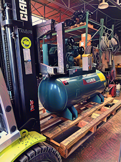
MODEL C-100 TWO
STAGE AIR COMPRESSOR PARTS AND SERVICE

Base mounted Large Industrial compressors are capable
of outing large amounts of air at high pressures and come in single stage, two
stage, or high pressure varieties. They work off the same basic compressor
cycle that tank mounted units operate on. NOTE: As these units do not come with
a receiver tank, the installation of safety valves in the discharge line is the
responsibility of the end user.


Maintenance
For the first weeks, the compressor needs time to “break in.”
The belt requires time to stretch and fit into the surface of the pulleys. The
piston rings need time to seat themselves into the cylinder walls, and bearings
need to wear into place. For the first 100 hours or so, the compressor will
consume higher than normal amounts of oil until the break in process is
complete.
FIRST MONTH MAINTENANCE
•
• Check oil level at the beginning of every week, fill as
needed, see oil subsection.
•
• Check belt tension at the beginning of each week and tighten
as required, see belt tension subsection.
•
• Check bolts, pulley clamp screws, and jam nuts for tightness.
Torque if necessary (see bolt torques subsection)


Maintenance Schedule
To assure maximum
performance and service life of your compressor, a routine maintenance schedule
should be developed. A sample schedule has been included to help you develop a
maintenance schedule designed for your particular application. Time frames may
need to be shortened in harsher environments or during periods of extremely
heavy use.


DAILY MAINTENANCE
•
• Check oil level. Check oil for discoloration and filth. Drain oil
and replace if required.
•
• Drain drip legs and traps in air distribution system.
•
• Open drain cock located at the bottom of the tank to relieve
condensation.
•
• Drain intercooler (Large Industrial)
•
• Check for oil leaks.
WEEKLY MAINTENANCE
•
• Manually operate the pressure relief
valves to be certain they are working.
•
• Clean the cooling surfaces of the
intercooler and compressor.
•
• Check the compressor for air leaks.
•
• Check the compressed air distribution
system for leaks.
•
• Check Oil Pressure, record reading at
oil change (Large Industrials)


MONTHLY MAINTENANCE
•
• Check motor belt tension.
•
• Check fan belt tension (C200, C260,
and C300).
•
• Check bolt torques, pulley clamp
screws, and jam nuts for tightness. Torque if necessary
•
• Inspect entire air distribution
system for leaks.
•
• Check all connections (mechanical
and electrical) and tighten as necessary.
EVERY THREE MONTHS
•
• Change oil (more frequently in
harsher environments).
•
• Inspect valves for rust, wear, and
carbon build up
•
• Check air filter for cleanliness and
replace if necessary
•
• Replace Oil filter and clean oil
strainer (Large industrials)
EVERY SIX MONTHS
•
• Replace air filter
MASTERLINE SERIES CAP200 Page 31 of 47 REV K JULY 2018


Oil
FS Curtis MasterLine compressors require a 500h
break in period and units are factory filled with the needed lubricant for the
break in period (FSC-1000 for ML, FSC-1000A for all Large Industrials). After
the break in period is complete, drain the oil and replace with required oil
for your compressor listed below. NOTE: Basic Pumps are not filled from the factory!
FS Curtis manufactures two different
lubrication systems for Masterline compressors.
The compressors D96, D97, C79, C89, C98, and
C100 use an oiling ring system. Use ISO68
FSC-1000 Premium Reciprocating Compressor Lubricant. This oil is specially
formulated for Curtis Reciprocating Air Compressors and is a non-Detergent type
oil with anti-foam, anti-rust and oxidation inhibitors.
Use ISO100
FSC-1000A for break in and regular use if ambient air temperatures
exceed 90°F.
Large industrial units C200, C260, and C300
have an oil pump system and operate under very high air pressures and
temperatures. Use ISO100 FSC-1000A.
This oil is blended for FS Curtis large industrial units.
For Large Industrials C150H, C260H, and C300H,
use ISO100 FSC-1000S synthetic
oil. For all other large industrials, use ISO100 FSC-1000A. For proper lubrication the compressor shall not
be operated below the minimum or above the maximum R.P.M. recommended for the
various models.
1. Maintain oil level mid-way

H&K AIR COMPRESSORS
DALLAS, TEXAS


MODEL C-100 TWO
STAGE AIR COMPRESSOR PARTS AND SERVICE


.jpg)


